
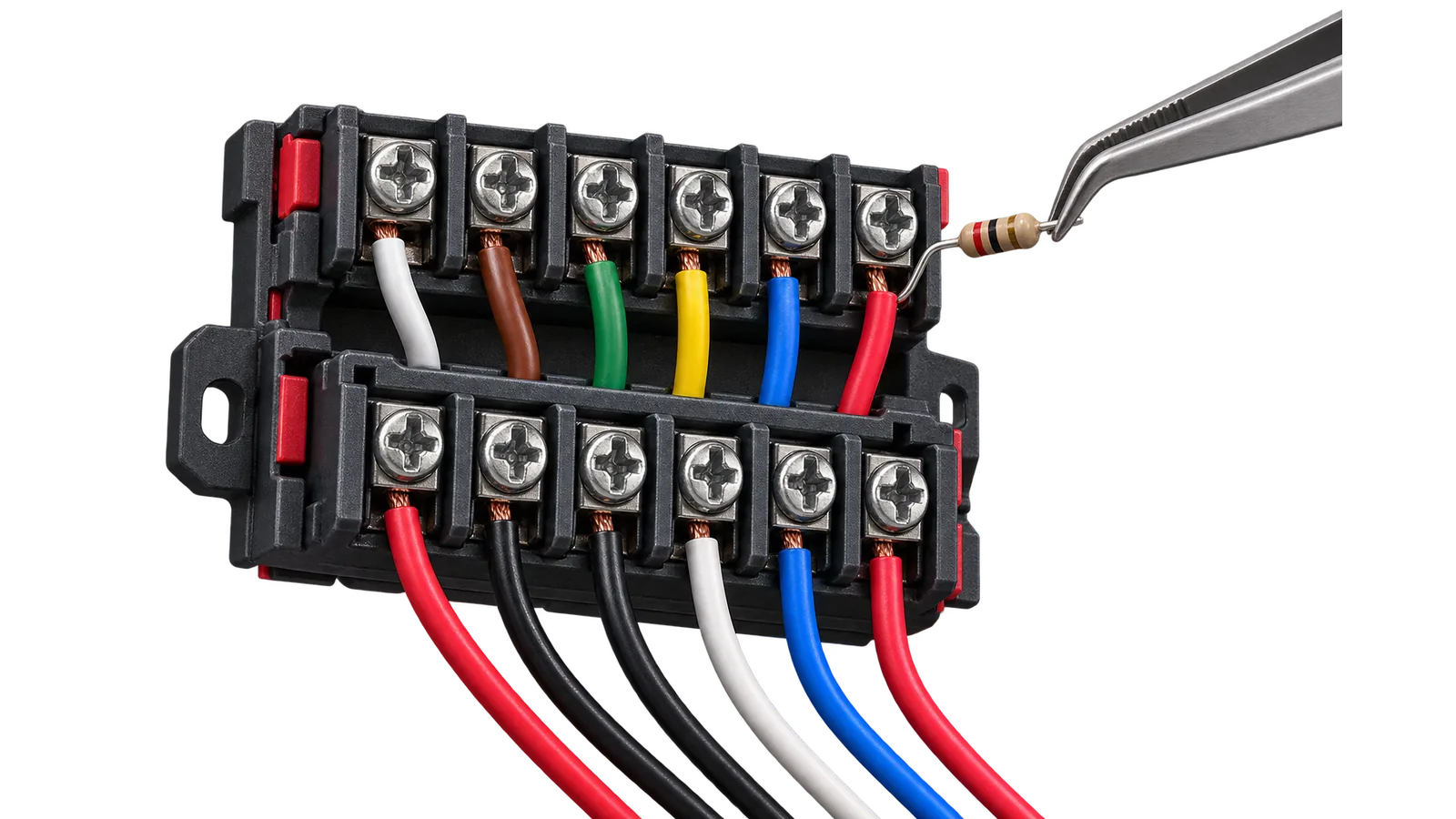
The panel has 24 loops, each terminated with a 7.5 kΩ end-of-line resistor — that is how it tells normal from a break or a short. Fire and burglary detectors go on separate loops: their events follow different logic at the console.
You will need
Multimeter, end-of-line resistors, labels, site drawing
Important
Do not mix fire and intruder detectors in one loop: the console handles the two event types differently.
- 1
Map the loops
Follow the site drawing to assign detectors and label every loop before wiring.
- 2
Wire the fire loops
Fire detectors go to loops marked as fire, with an end-of-line resistor at the end of the line.
- 3
Wire the intruder loops
Intruder loops follow the site areas so that parts can be armed separately.
- 4
Measure resistance
Check every loop with a multimeter. A value off the calculated figure means an open or a short.
- 5
Check the events
Trigger a detector in each loop and confirm the console received the right number and type.
The result
Every detector sits on a labelled loop, resistances are in range, and each trigger reaches the console with the right number and type.